Heat Pump Rig
January - May 2024
I took a class called ME-360: Engineering Experiments junior spring semester. Our final project was to build a tabletop sized heat pump rig from scratch.
Context
Our assignment was to research, design, review, part orders, build, and modify a tabletop heat pump rig that will be used for educational purposes. The rig will have readable parameters to measure work, efficiency, mass flow rate, temperature, pressure, rpm, coefficient of performance, enthalpy, entropy, quality, and phase of (1) refrigerant loop and (2) water loops. These readable parameters will be compared to varying compressor speeds for students to better understand optimization of heat pump systems. And most importantly it needs to be safe, the refrigerant we were using (as environmentally conscious as it was) is extremely flammable and must be handle by a licensed professional.
If you come from an engineering or engineering parallel background feel free to skip to the next section. But if you want to learn a little bit more about how a heat pump works the below sections will bring you up to speed.
How Does A Heat Pump Work? (In 5 Levels Of Increasing Complexity)
Level 1 - Overview
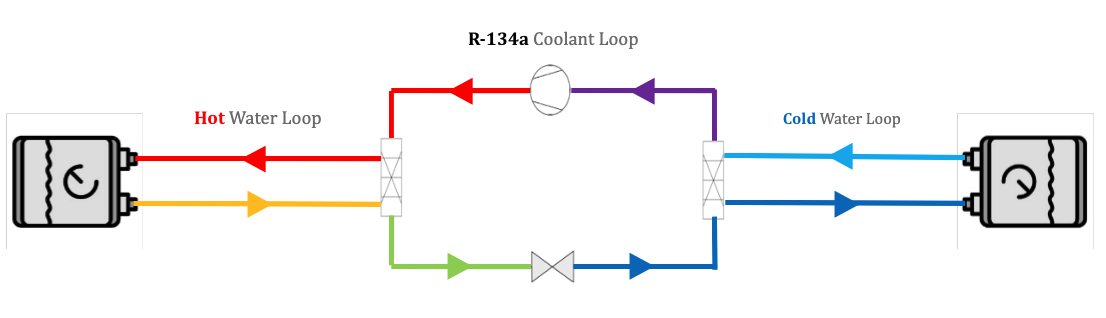
Our heat pump has 3 closed off loops that run counter flow to each other. The arrows in the diagram represent the direction of flow. The central loop is filled with a mostly liquid refrigerant. And the loops on the left and right are water loops (left is hot water, right is cold water). The loops meet at the two rectangular boxes, these are called the heat exchangers and its where all the energy transfer happens. A heat pump is a constant cycle of removing the right side of its heat and supplying the left side with that heat.
Level 2 - Overview
A better way of describing this heat is with thermal and electrical energy. As the saying goes, “you have to spend money to make money” this also applies to heat pumps in that “in order to move heat you must first add more heat to the system.”
I want to first point your attention to the electric energy being inputted into the system. You might be asking yourself, why on Earth are we adding electrical energy? The electrical energy is what keeps the refrigerant flowing and makes sure the heat keeps moving through the system.
A cool way of thinking of this is when you touch a cold piece of metal. It’s cold to the touch because it’s pulling heat out of your hand. I think I’m crazy for this but a good conceptual way to understand thermodynamics is to think of the cold being pulled from your hand and simultaneously pretend to be the cold piece of metal being touched by a hot human hand.
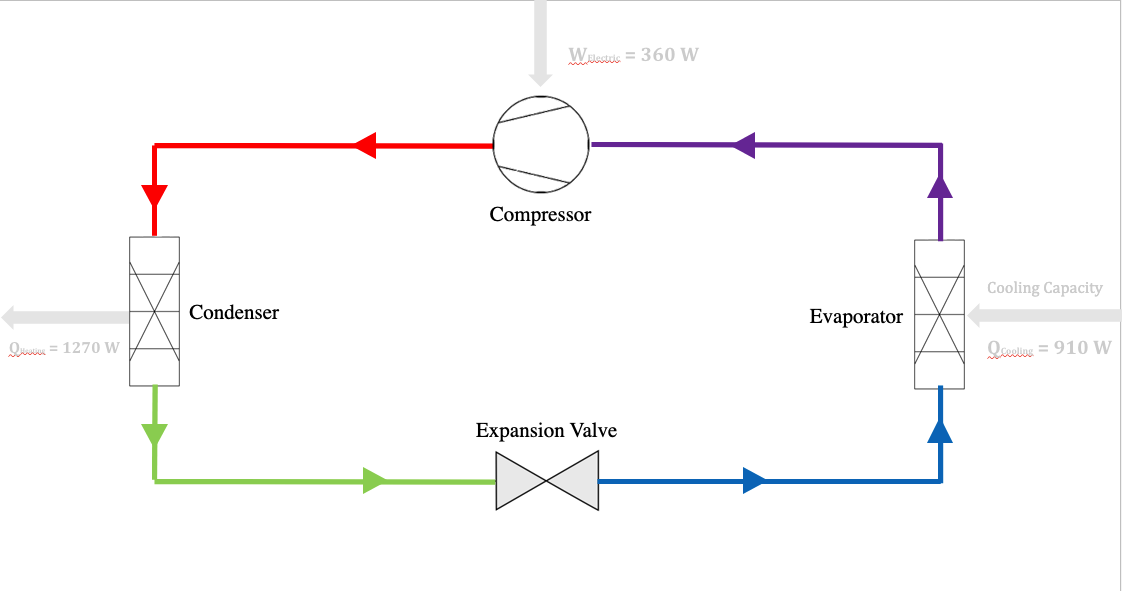
If you have a keen eye, you’ll have noticed that the energy input is equal to the energy output.
Input QCooling (910 W) + WElectric (360 W) = QHeating (1270 W)*
*This is ideal, meaning it won’t actually be 100% efficient like this in the real world.
Level 3 - Overview
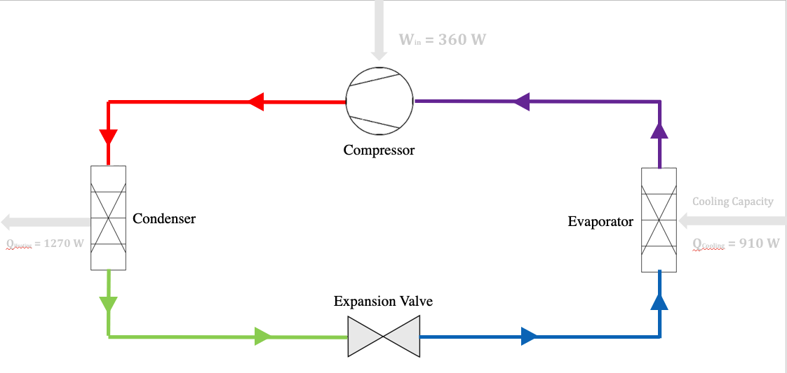
The heat pump compression cycle involves four key components, each integral to its operation. Beginning with the compressor (top of the diagram), it pressurizes the refrigerant, elevating its temperature to facilitate efficient heat exchange. From there, the refrigerant flows into the condenser, where it releases heat to the surrounding environment, undergoing a phase change from vapor to liquid. Following the condenser, the expansion valve regulates the refrigerant's flow, reducing its pressure and temperature as it enters the evaporator. Finally, in the evaporator, the refrigerant absorbs heat from the designated space, completing the cycle by transitioning back into a vapor state for recirculation through the compressor.
Level 4 - Stages
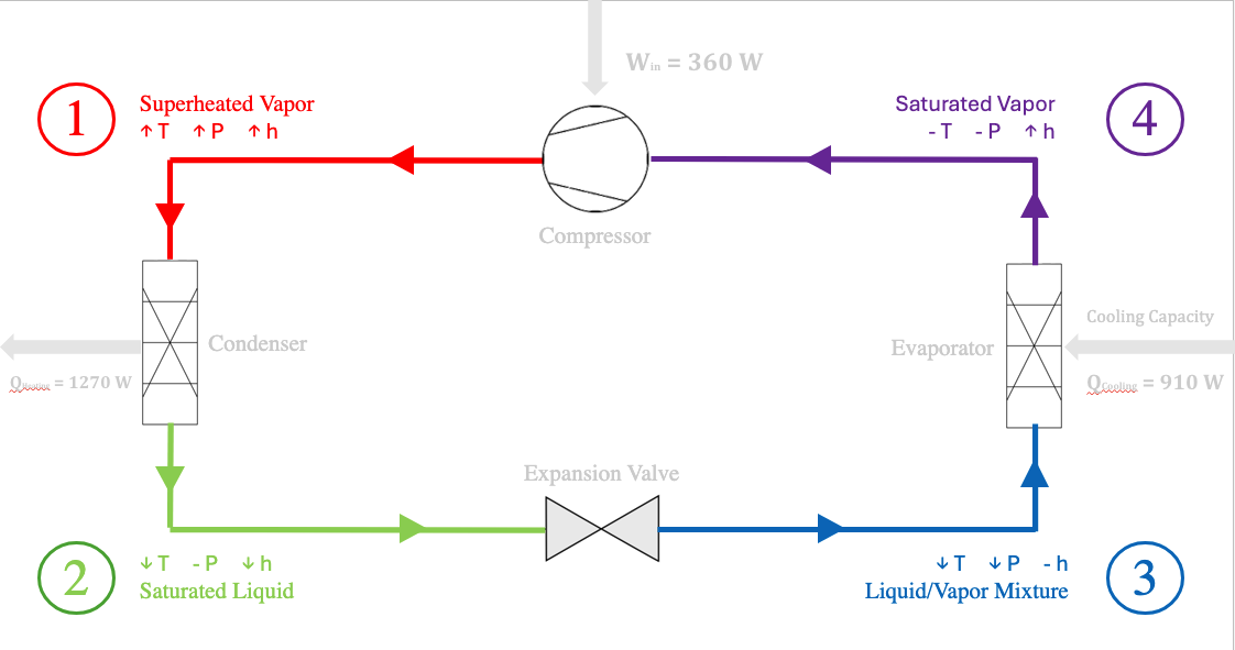
In the heat pump compression cycle, the refrigerant passes through distinct phases. In Stage 1, the Superheated Vapor phase, the refrigerant exits the compressor as a high-temperature, high-pressure vapor. In Stage 2, the Subcooled Liquid phase, it cools in the condenser, reducing its temperature while maintaining pressure. In Stage 3, the Liquid Mixture phase, the refrigerant passes through the expansion valve, lowering its temperature and pressure. Finally, in Stage 4, the Saturated Vapor phase, it absorbs heat in the evaporator, maintaining constant temperature and pressure, preparing for compression again.
In the expansion valve a phase change occurs, meaning a substantial amount of the liquid refrigerant turns into vapor. This process is called latent heat, which changes the phase of the substance without changing its temperature. This allows for the transfer of large amounts of energy with relatively small temperature changes.
Level 5 - Enthalpy (aka the final boss of thermodynamics)
Kicking the assess of every college engineer that learns about it for the first time, enthalpy has an undefeated track record against college engineers who attempt having a solid conceptual understanding of what it means in the first place.
Here is my best attempt and vaguely defining it. Enthalpy is a measure of the total energy of a system, including both its internal energy and the product of its pressure and volume.
I bring this up because that’s how we found how much work was being done back at Level 2. Full circle moments are cool.
Product Development
Why Heat Pumps?
They are more efficient than traditional heating or air conditioning methods.
Design
Our initial design laid out the separation and formatting we wanted the rig to have. This rig is intended to be used for educational purposes in the future so our aim was not to optimize how much space it took up, so spacing things out would give us more room for graphics and readable parameters.
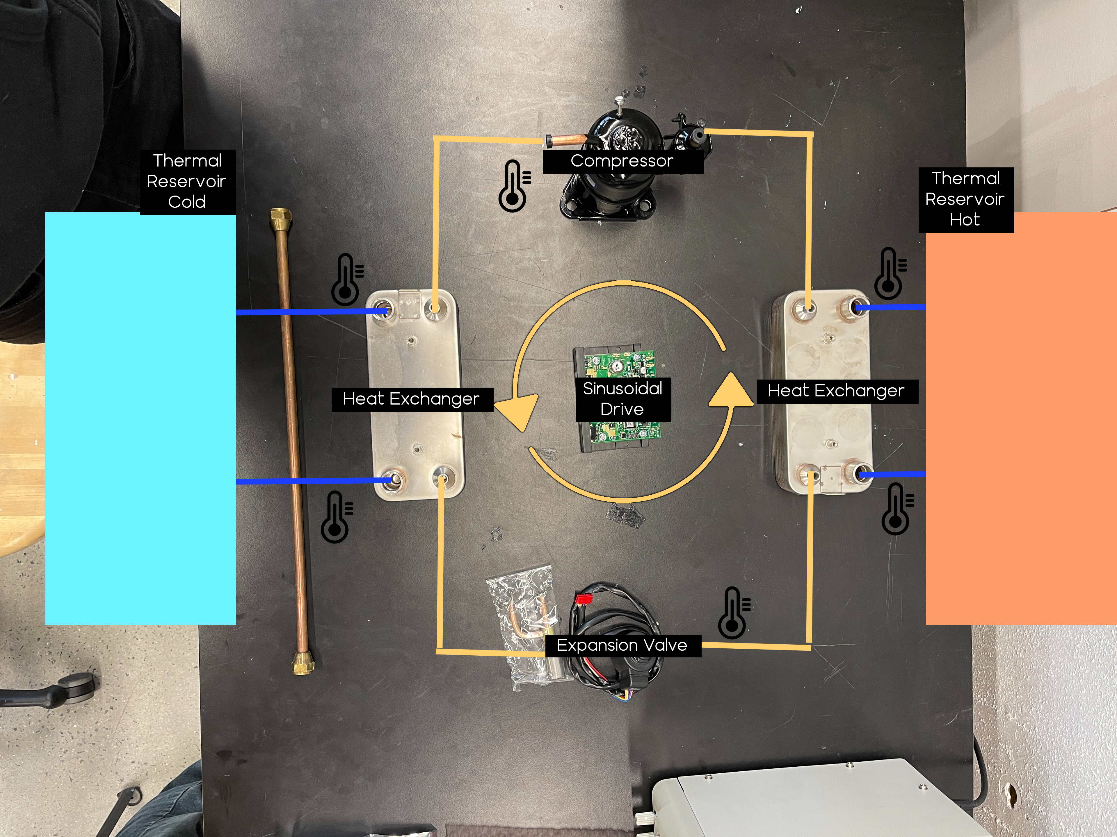
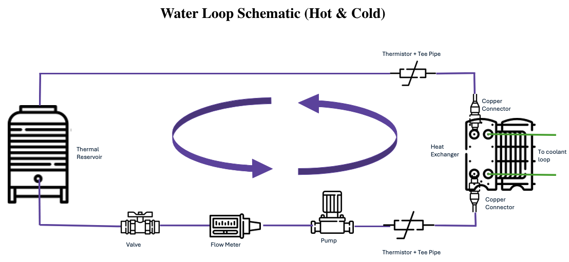
The two loop schematics above are for the refrigerant line (left) and the water line (right). This laid out the basic design of the entire rig. Btw, the water line is duplicated, meaning the hot water line and the cold water line are just mirrored versions of each other.
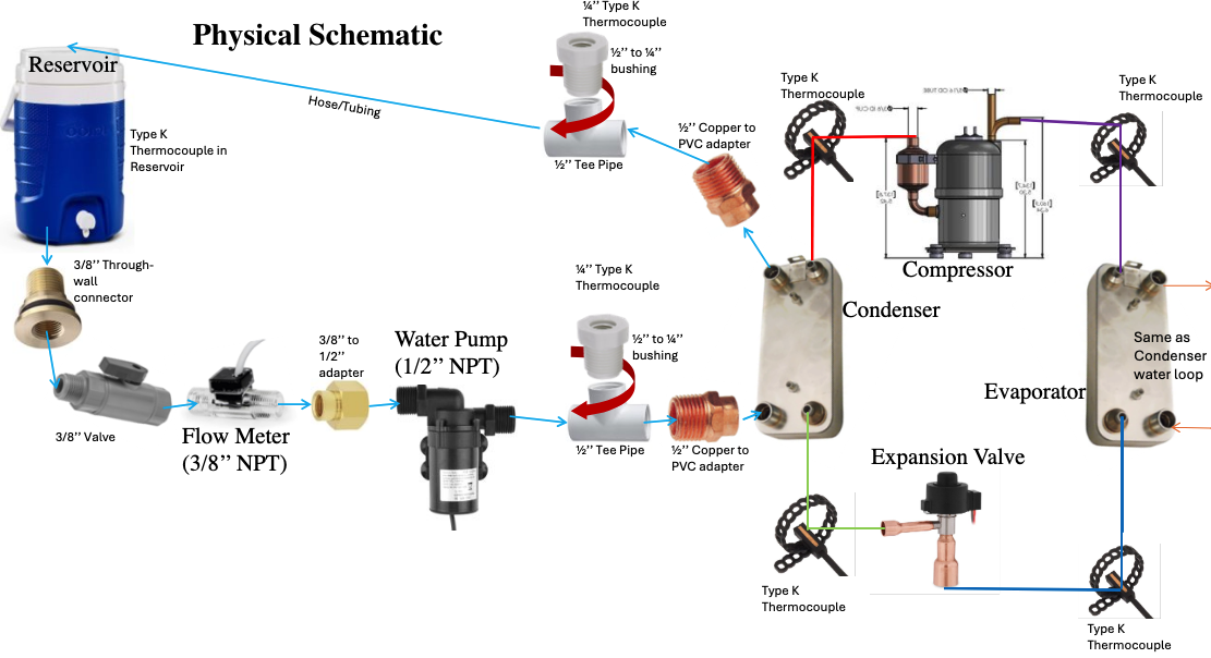
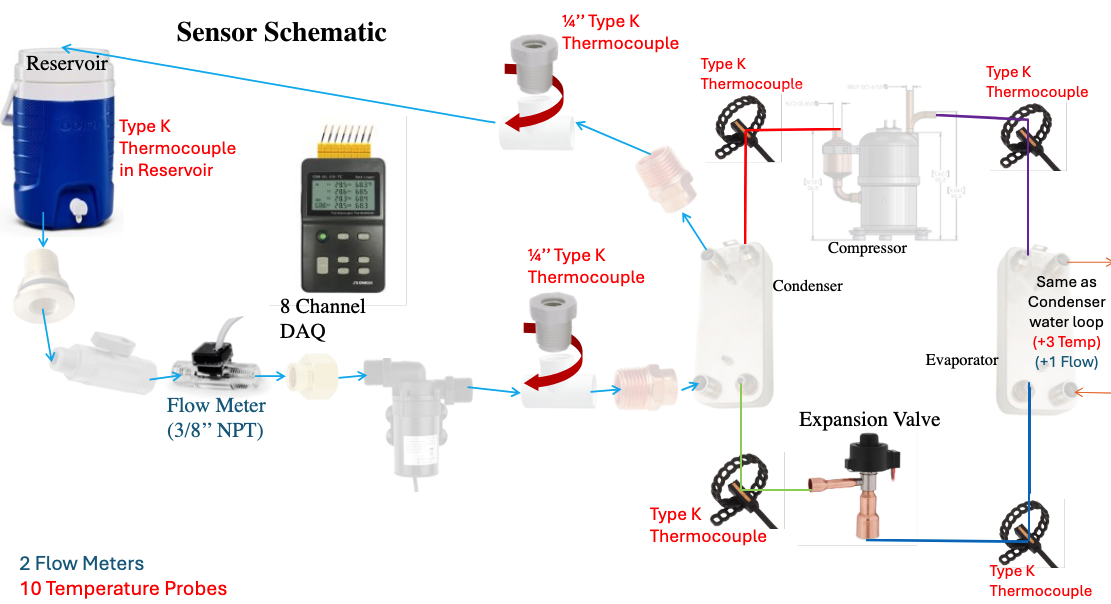
Above is a physical and sensor schematic of the water line. We used a total of 10 temperature, 2 flow rate, 6 pressure, 3 energy in/out, and 1 system efficiency sensor for all of our data collection.
The water line was tricky because it contained so many small pieces, each of which served different functions and needed to fit perfectly. With 3 different types of NPT fittings we managed to connect everything together.
Calculations
I did some calculations on an ideal vapor compression cycle, which is just technical engineering jargon for "what we expect the heat pump to do when we turn it on." Below is a table for what that looks like.
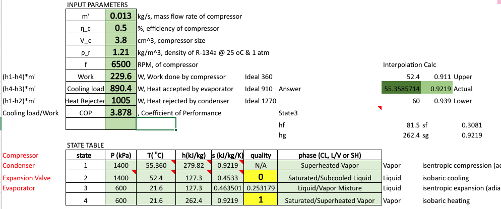
If you're curious for a more in-depth engineering analysis of how I calculated all of these values, I have an appendix at the bottom that walks you through that.
Order Parts
Here's a short list of everything we ordered.
| Component Name | Quantity | Price |
|---|---|---|
| ½’’ Copper Pressure Cup x MIP Male Adapter Fitting | 4 | $8.52 |
| ½’’ Sch 40 PVC Tee Fipt | 4 | $7.44 |
| ½’’ MNPT x ¼’’ FNPT Schedule 40 White PVC Threaded Reducing Bushing | 4 | $9.44 |
| ½’’ x 3/8’’ Sch 40 PVC Reducing Female Adapter – Soc x Fipt | 2 | $1.52 |
| Pipe Plug Thermocouple Probes with NPT Fitting and Lead Wire | 2 | $151.80 |
| Twidec/2Pcs ¼’’ Screw Probe Temperature Sensor K Type Thermocouple 2 Meters Cable | 2 | $23.98 |
| 8 Channel Handheld Thermocouple Thermometer/Data Logger | 1 | $398.39 |
| Igloo Portable Sports Cooler Water Beverage Dispenser With Flat Seat Lid | 2 | $33.98 |
| 10 Set K type Thermocouple M/F Temperature Testing Probe Connector | 1 | $17.59 |
| Aquasol Plumbing Solder, Silver Bearing, ½ Lb Spool | 1 | $14.85 |
| Plumbers PTFE Pipe Sealant Tape Flex Seal Tape Waterproof | 1 | $3.99 |
| Brass Bulkhead Fitting – 3/8’’ NPT Female x ½’’ Straight Male Thread Tank Connector with 2 Rubber Rings for Water Tower Tank Barrels | 2 | $17.98 |
| 3/8’’ Gray PVC On/Off | 2 | $15.58 |
| 3PCS Brass Reducer Adapter, 3/8’’ NPT Female to ½’’ NPT Female Thread, Hex Reducing Pipe Fitting Coupler Nipple Connector for Water/Oil/Gas | 1 | $10.99 |
| 24V 25A Power Supply | 1 | $59.90 |
| T38 Model Compressor | 1 | $725 |
| Steel Plate Heat Exchanger | 2 | $550 |
| Sanhe Expansion Valve and Stator Coil | 1 | $65 |
| Turbine Flow Meter | 2 | $186.70 |
| Copper Pipe Temperature Sensor | 6 | $44.16 |
| Water Pump | 2 | $48.58 |
| Copper Pipe ¼" | 6’ | Provided by Cooper |
| ¼’’ Flare Charge Port | 2 | Provided by Cooper |
| Marine Adhesive | 1 | Provided by Cooper |
| Dish Soap | N/A | Provided by Cooper |
| Vacuum Pump | 1 | Provided by Cooper |
| Blow Torch | 1 | Provided by Cooper |
| Pipe Cutter | 1 | Provided by Cooper |
| Pipe Bender | 1 | Provided by Cooper |
| ½’’ Hose | 6’ | Provided by Cooper |
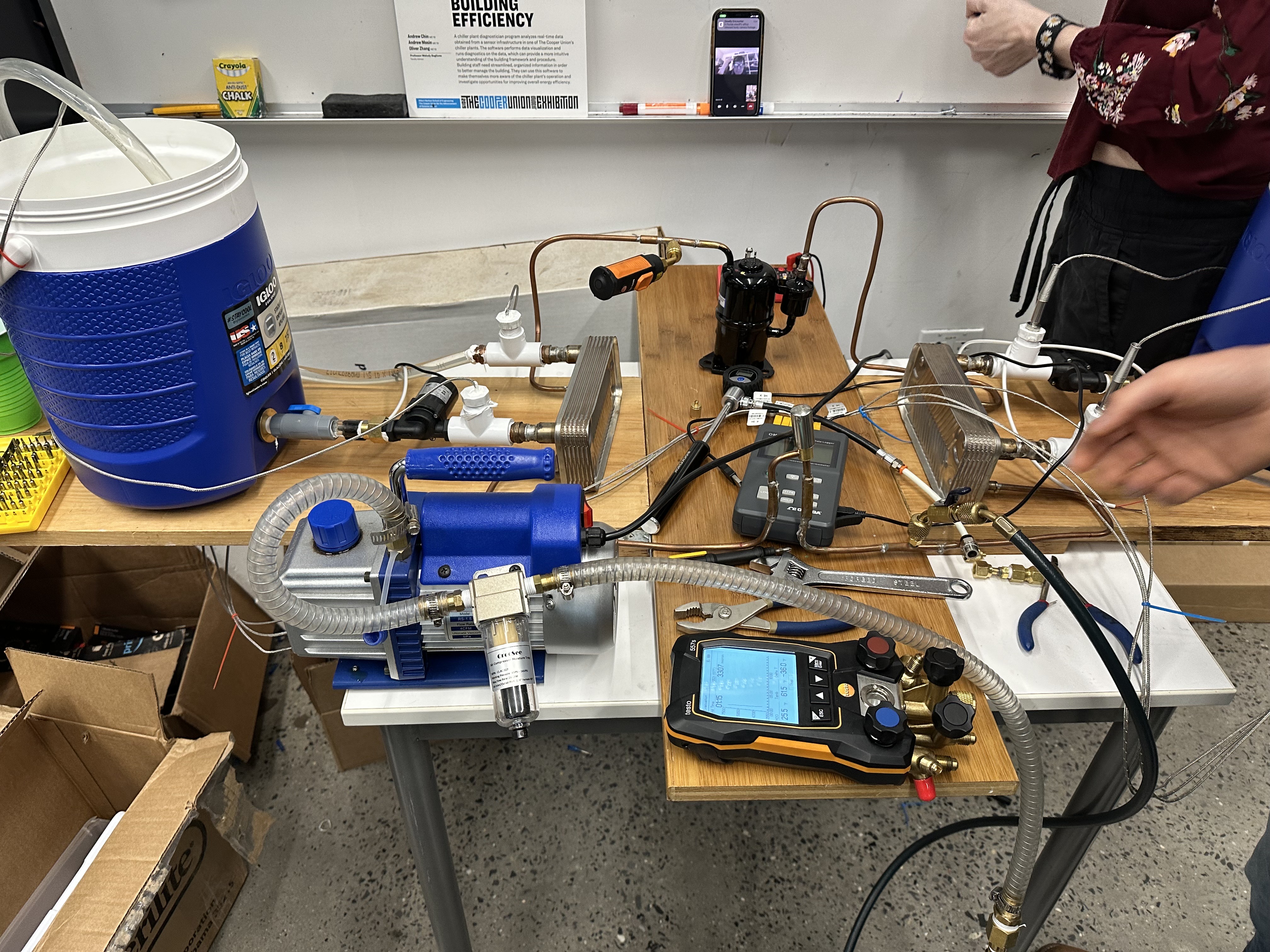
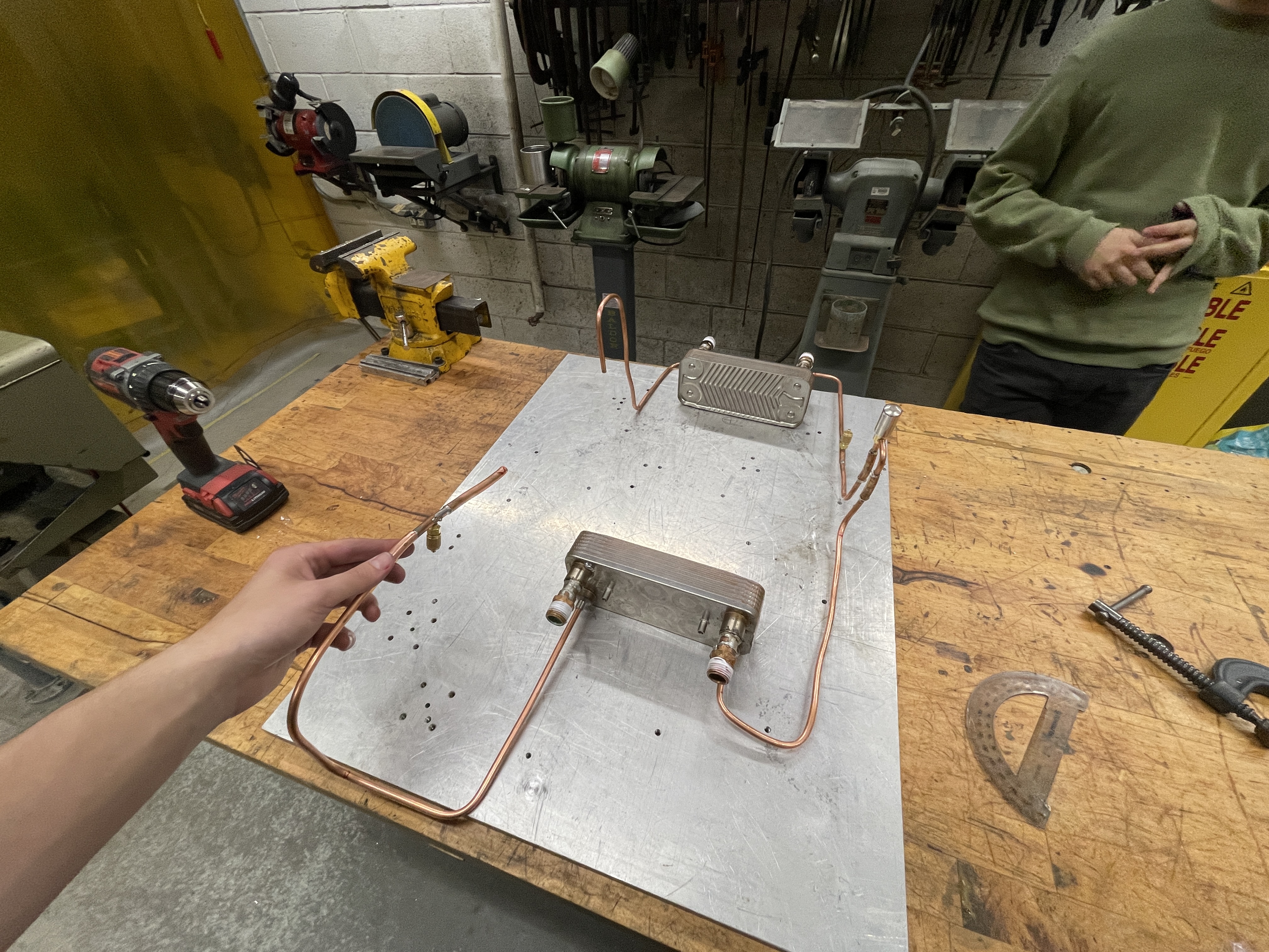
Build
Building this rig was SOOO much fun. I had a blast seeing everything finally come into fruition.
We soldered copper. Probably the most badass thing I've done at Cooper.
For safety measures we tested the refrigerant line for any leaks. Standard procedure is to add soapy water into the line, pressurize it, and see if any bubbles form at potential leak spots. Luckily we didn't see any bubbles form so we were finally ready to add refrigerant to the system.
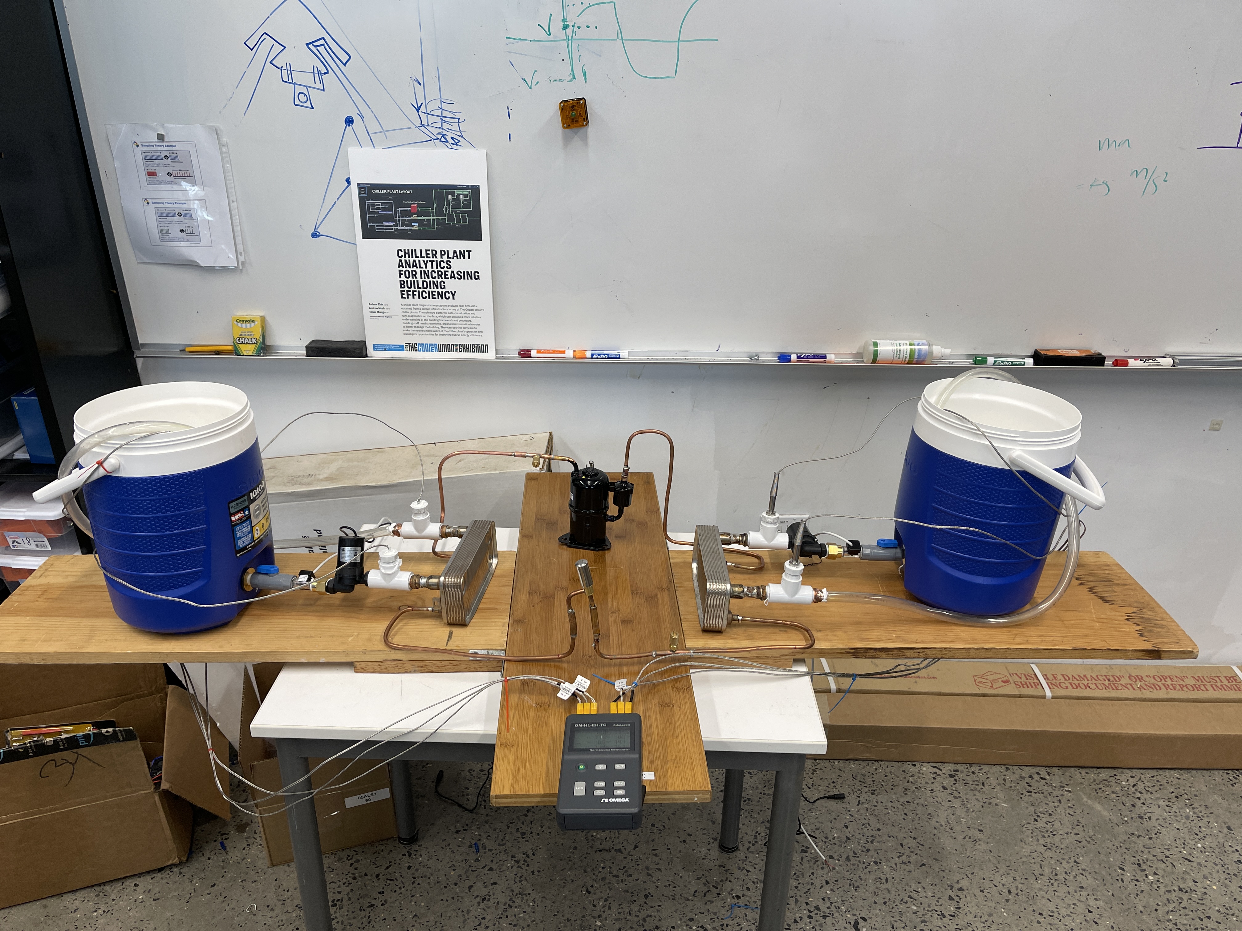
Results
We ran out of semester before we ran out of ideas to implement into the heat pump rig. A couple of the things we didn’t and wish we had more time for include: making the rig more educational (adding visuals and labels), creating a power supply from scratch to be able to all components using a central power source, and finally adding a small LED display which showed all of the readable parameters updating in real time.
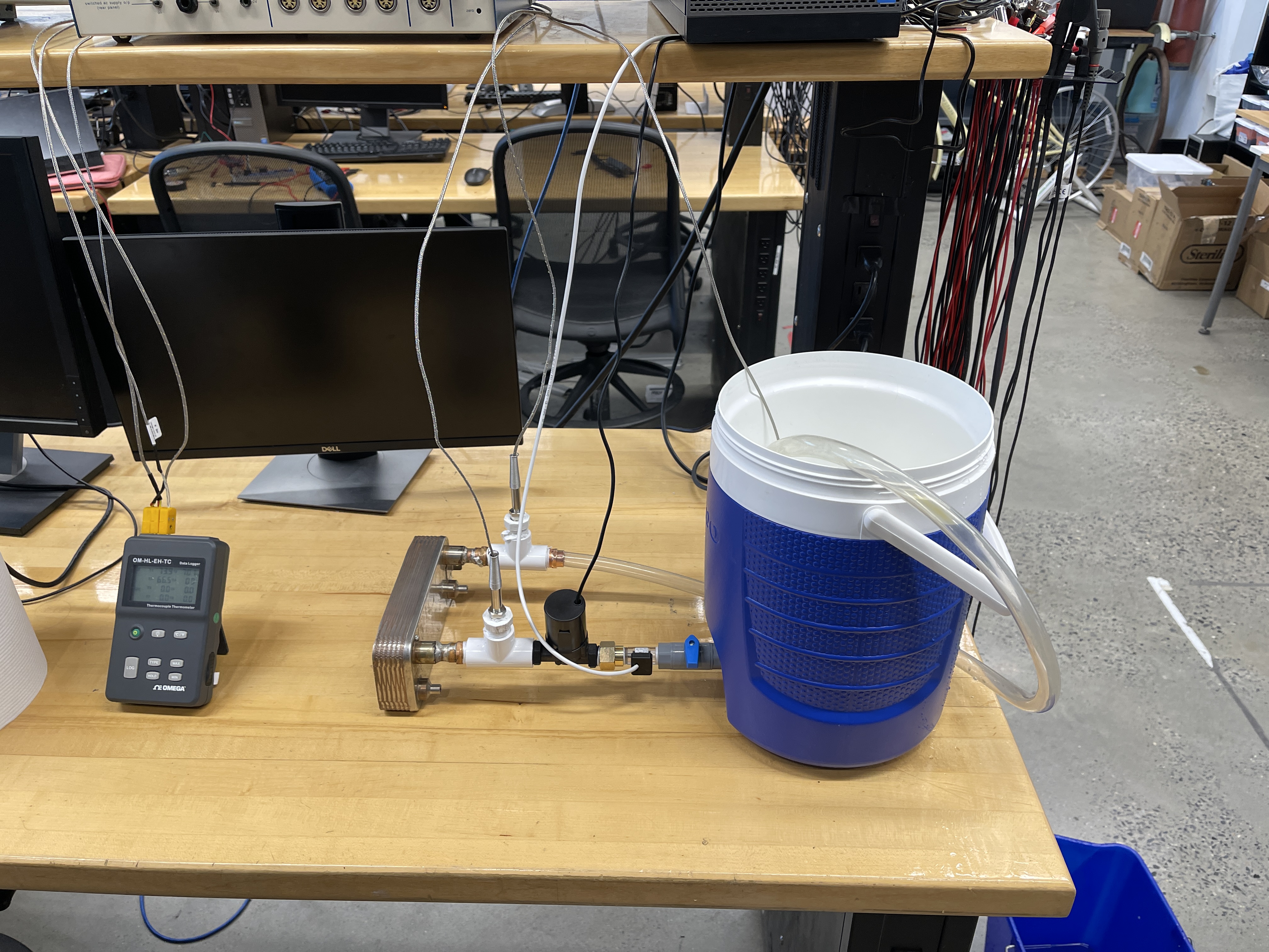
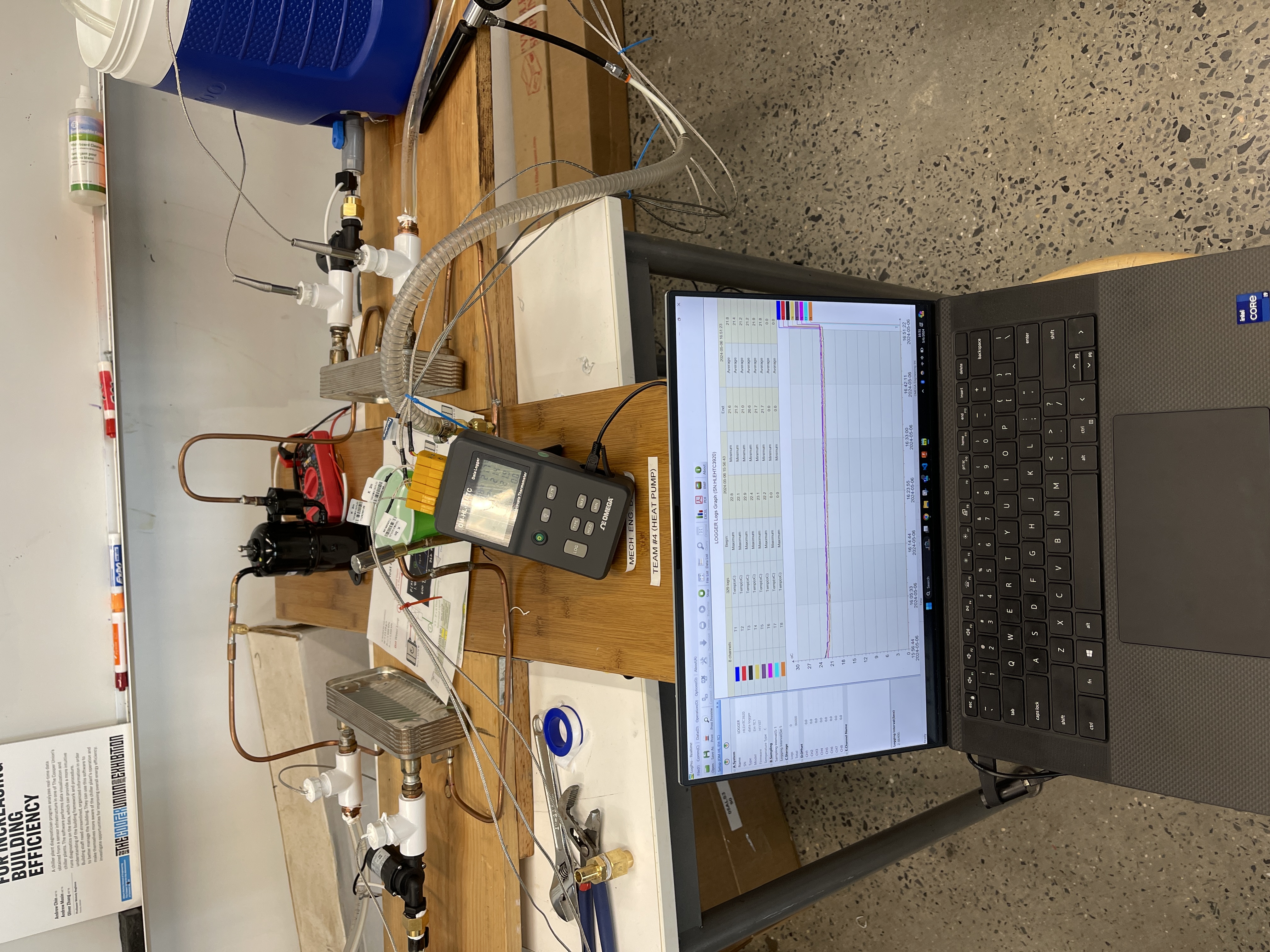
Here’s what our final rig looked like, as well as some of the readable parameters I was able to get with a laptop connected directly to our DAQ (Data Acquisition Unit).
Appendix: Example Vapor Compression Cycle Calculation
To summarize the calculation process of the heat pump in terms of a refrigeration cycle, we start by gathering data from the manufacturer's specifications. For instance, if we have a compressor that can push 13 grams per second of refrigerant and can produce a pressure of 1,400 kPa with a required suction pressure of 600 kPa, we input these values into our calculations. Remember that with those three initial conditions we can calculate the rest of the refrigeration system.
m' = 13 g/s, P_outlet = 1,400 kPa, P_inlet = 600 kPa
First, we determine the properties of the refrigerant at different stages of the cycle. For example, at stage 4, between the evaporator and the compressor, we know the pressure and that it's a saturated vapor. We use R-134a thermodynamic properties tables to find the corresponding temperature, enthalpy, and entropy at this pressure.

R-134a Thermodynamic Properties Table (Saturated Vapor)
P_inlet = P_4 = 600kPa, T_4 = 21.6 oC, h_4 = 262.4 kg/kJ, s_4 = 0.9219 kJ/kg/K, quality = 1
Moving to stage 1, leaving the compressor, we need to consider the isentropic nature of the process, where the entropy at stage 1 equals that at stage 4. We then use superheated vapor tables to find the enthalpy and temperature at this pressure and entropy.

R-134a Thermodynamic Properties Table (Superheated Vapor)
The entropy we are looking for is 0.9219. However, looking at the Superheated Vapor list, we can’t find that specific value, it’s between two values, so we linearly interpolate the values.
Doing this for each of the units we get,
P_1 = 1,400kPa, T_1 = 55.4 oC, h_1 = 279.8 kg/kJ, s_1 = 0.9219 kJ/kg/K, quality = N/A
At stage 2, before the expansion valve, we know the pressure is the same as stage 1, but it's a saturated liquid. Using the saturated liquid tables, we find the temperature, enthalpy, and entropy.

R-134a Thermodynamic Properties Table (Superheated Vapor)
P_2 = 1,400kPa, T_1 = 52.4 oC, h_1 = 127.3 kg/kJ, s_1 = 0.4533 kJ/kg/K, quality = 0
Stage 3, after the expansion valve, is trickier as it's a mixture of liquid and vapor. We find the temperature using the temperature at stage 4, and the enthalpy remains constant from stage 2. Knowing the pressure, we determine the entropy by first finding the quality of the refrigerant, indicating how much is liquid or vapor, and then using this to find the entropy.
Quality is found with this equation,
𝑥4=ℎ4−ℎ𝑓ℎ𝑔−ℎ𝑓 𝑥 4 = ℎ 4 − ℎ 𝑓 ℎ 𝑔 − ℎ 𝑓 , the hf = 81.5, sf = 0.308, hg, 262.4, sg, 0.9219, so x4 = 0.253178552
Finally we calculate entropy using,
s_4 = s_f + x_4 * (s_g - s_f)
With the properties of the refrigerant at each stage determined, we can calculate various parameters, such as the work done by the compressor, the cooling load on the evaporator, and the heat rejection by the condenser. These calculations help us evaluate the efficiency of the system, often expressed as the coefficient of performance (COP), which relates the cooling provided to the work done by the compressor.
Work done by compressor, evaporator cooling load, condenser heat rejection, and coefficient of performance,
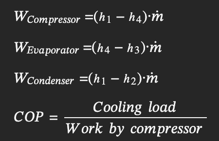
W_compressor = 360 W, W_Evaporator = 910 W, W_Condenser = 1270 W COP = 3.9